
Background information
Where dress up and open world meet: Infinity Nikki
by Kevin Hofer
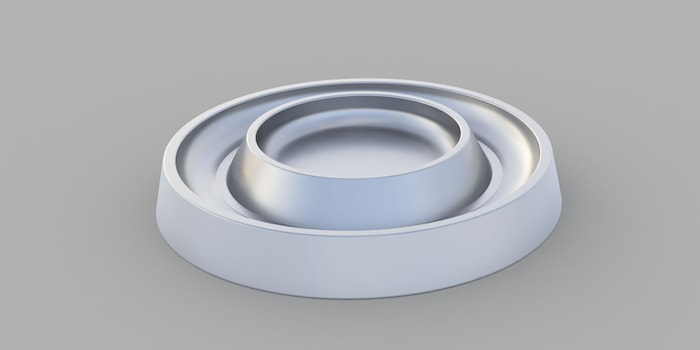
My new favourite gadget is going down a treat with the Community too. Since the Play Tray is no longer available to buy, I’m going to show you how to design your own on your computer. If that sounds like too much hard work, simply download my template.
«Great :( I wanted to order one right away» and «You little trigger [sic] you ;-)» are just two comments posted under my Play Tray article. In the run-up to publishing it, I was aware I’d get this sort of response. A desk accessory, the Play Tray is both a storage solution for screws and a fidget toy in one. Who wouldn’t want something like that? The comments stem from the fact that this trusty product is no longer available to buy. That’s why I’m going to show you how to design something similar in CAD Fusion 360. CAD stands for Computer Aided Design. Once your design is ready, you can hand it over to a contract manufacturer who’ll make the Play Tray for you. Since I’ll be breaking it all down for you, it should take you about two hours from starting the program to finishing the design. Alternatively, you can save yourself the effort and skip to the end of the article, where you can download my template.
Fusion 360 is free for personal use. Even if it isn’t your first language, I recommend you install the program in English. This is handy if you want to work with tutorials in English later. As with other CAD programs, there are various ways of building the object. I’ll show you my approach, however, there might be simpler ways of doing it – I’m not a pro.
The best way to get familiar with the program’s navigation is to watch the following video. It’s required viewing if you’re going to be able to follow the instructions.
Once you’ve installed and opened the program, you’ll see a new project. On the left you’ve got your file browser, on the right, your workspace. Below that, there’s the timeline, above it, the command bar. The whole thing should look like this (without the timeline entries):
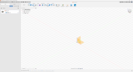
The first thing you need to do is create the Play Tray’s basic shape. In the workspace, you’ll see three orange areas and axes. This is called the Origin. If you don’t see it, go to the menu in the upper-left corner of the workspace and click on the eye next to Origin. By doing this, you can cause things to disappear and reappear.
Right click on the plane on the bottom (XY Plane if you click on it) and select Create Sketch. In this view, you’ll be able to sketch. Since the basic shape of the Play Tray is a circle, that’s what you’ll need to draw. To do this, press the S key on your keyboard. This opens a context menu at the position of the mouse pointer. Here, you select Center Diameter Circle. If it doesn’t appear in your menu, type it into the context menu’s search bar. Now, move the mouse pointer to the point of origin (the point in the centre of the workspace) and left-click it once. You can now draw a circle. Expand it until it reaches 95 millimetres in diameter. Alternatively, you can type 95 on your keyboard. And there you have it – a circle.
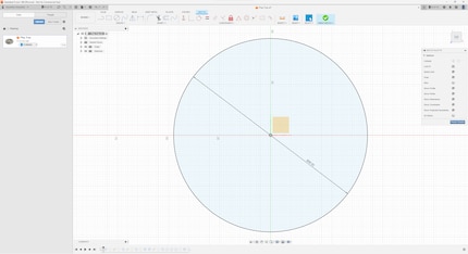
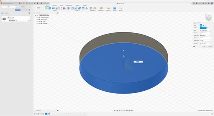
However, this circle is only two-dimensional. To construct a three-dimensional object, press the E key. This stands for Extrude in Fusion 360. The Extrude menu will now appear on the right. Using this, you can drag a profile (in this case, the circle) upwards and create a body from the sketch. Don’t let the deluge of specifications in the menu faze you. Everything’s correct as it is for now. On your circle, you’ll see an arrow, where you’ll have the option to type in numbers. The Play Tray is 14 millimetres high at the edge. Type in this number and click OK in the menu on the right. You’ve now created the base plate.
Next up is the indentation for the ball. To do this, create another sketch. Right-click with on the upper right corner of your base plate and select Create Sketch. This creates the sketch on the top of the body, and not on the XY plane. Hit the S key and select Center Diameter Circle again. Start at the point of origin in the centre and make the circle 71 millimetres in size. Once you’ve drawn it, click Finish Sketch on the right.
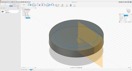
In order to cut along the circle you’ve just generated, you need to create something to help you. This is where the «Plane along path» tool, which allows you to construct a new plane on a path, comes in. To do this, click Construct in the command bar at the top and select «Plane along path». Take the inner circle you sketched before as your path and click OK.
Now, use the plane you’ve generated to create another circle. To do this, right-click on the new plane and select Create Sketch. You know the rest:
All you have to do now is cut out the indentation by creating a sweep. To do this, go to the command bar and click Construct, then Sweep. You now need to select the profile or profiles as well as the path where you want to create the sweep. Select the circle you’ve created on the new layer as your profile, designating the inner circle on the top of the base plate as your path. To switch from profile selection to the path selection, you have to click on Path in the menu on the right. This is what is should look like:
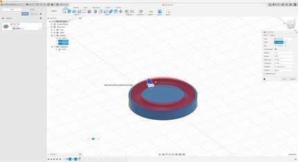
Now, you just have to click OK on the right and you’ll have cut out a lane for the ball. Well, almost. If you look at the Play Tray up close, you’ll notice that the lane isn’t completely round. The Play Tray is volcano-shaped towards the inside, while the bottom of the protrusion for the ball is flat for a short distance.

This «bottom of the volcano» is next. This involves clicking on the top of the body and creating a sketch in the same way as described above. You then create another circle again at the centre point. This has a diameter of 71 millimetres, so it’s the same size as the path you created for the protrusion. That’s because you’re now adding material to it. To do this, press E for «Extrude» and select the outside, i.e. the ring of the circle you’ve just created. Enter -7 millimetres for the distance. The minus is important here, because you want to extrude towards the bottom. In the menu on the right, select Join instead of Cut this time:
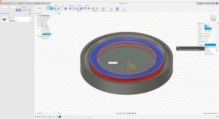
Things continue with, yep, you guessed it, a circle. Create a sketch at the top of the body. Then, starting at the centre point, sketch a 66-millimetre diameter circle. Now extrude again by pressing E, select the ring of the circle, type -6,7 and select Cut on the right. The surface for the ball will now be flat again instead of round.
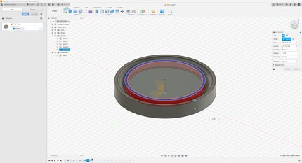
Before you get to the gradient, you’ll need to raise the inside of the play tray. This is because the «volcano» is higher than the outer rim. To do this, click on the top centre of the body, press E for «extrude», drag the selected area up by 4 millimetres, and click OK.
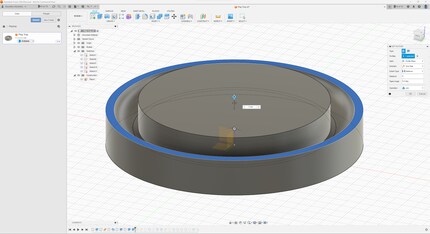
Time for the gradient. Go to the command menu at the top and click on Construct then «Plane along path». Select the circle shown in the following image to create the plane.
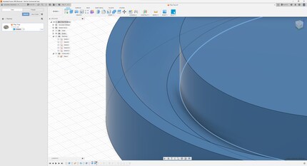
On this plane, you create a new sketch. For once, you’re drawing a right-angled triangle, not a circle. To do so, type S to open the sketch shortcut menu, then select Line. Place the mouse in the middle of the plane and circle and left-click once. Now drag the mouse upwards. Enter 11 millimetres for the height and 90 degrees for the angle. Now left-click once, then move the cursor towards the centre of the body. Here, select 6.6 millimetres for the distance, keeping the angle at 90 degrees. Finally, connect the line back to your starting point. Here’s what that looks like:
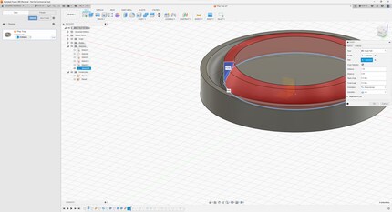
Now, you just have to create a sweep. To do this, go to the command menu at the top and click Create, then Sweep. For the profile, select the triangle you just created. If you can’t select it, you may have to hide the body first, as it’s possible that it could be covering your sketch. To do this, go to the menu in the top-left-hand corner of the workspace in the browser and click on the eye beside Bodies. For the path, select the same circle you used as a base for the last «plane along path». If you’ve hidden the body, display it again now.
The whole thing is starting to take shape – don’t worry, most of the work is done. The drawing is still missing the central pit designed for screws. To make it, create another circle on top of the body. This should be 56 millimetres in diameter. Press E again to extrude, cut out -8 millimetres and hey presto, you’ve got a pit for your screws.
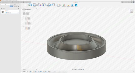
If you want, you can also construct an angled wall on the outside. To do this, follow the steps you took while creating the first one. Only, this time, draw the triangle outside of the body. I create mine three millimetres outside of it.
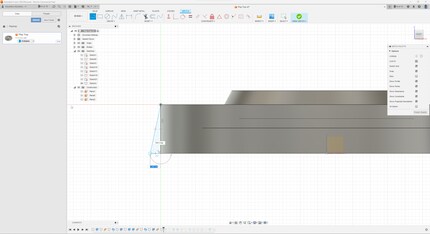
You’re now almost done with the top side. The whole thing still looks a little boxy, which is why I’ll round off the edges. To do this, type F for Fillet. You can now select all the edges you’d like to round off. In the following picture, you can see the ones I decided to go for. I choose a radius of 0.5 millimetres so that they’re not overly round.
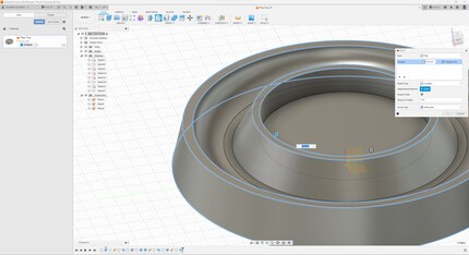
I also round off the screw storage area at the bottom. Here, I choose a fillet of 5 millimetres.
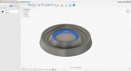
The only thing missing is the magnet. This goes on the bottom of the Play Tray, holding the screws in place on the other side. Rotate the object so you can see the underside. On this plane, create a new sketch and select your favourite tool – the circle. The size of the magnet will dictate the size of the circle. I’ve gone with a magnet size of 20 millimetres. To be able to fit it snugly into the recess, I create a circle with a diameter of 20.5 millimetres. All that’s left to do is extrude the recess. Here, I select a depth of 6 millimetres.
The Play Tray is complete. The computer version, anyway. You still have to get it made. The best way to go about this is to look for a contractor online. One of the many options out there is PCBWay. When I upload the Play Tray there to get a quote, one unit costs around 50 US dollars – not including shipping, of course. You can make it cheaper by teaming up with other people to place a bulk order.
You can download my model in STEP and STL format here. STEP stands for «Standard for the Exchange of Product model data». These files include complete 3D models, including geometry. The format is recommended for milling. The STL file stores information about a 3D model, with the surface of the model represented by interconnected triangles. This format is recommended for 3D printing.
From big data to big brother, Cyborgs to Sci-Fi. All aspects of technology and society fascinate me.
Interesting facts about products, behind-the-scenes looks at manufacturers and deep-dives on interesting people.
Show all